5, 4, 3, 2, 1 ….. !!! I’m not a pyromaniac, I promise.
This thruster uses H202 as it’s sole propellant; the reaction with Potassium Permanganate catalyst provokes a rapid decomposition into O2 and H20 and a corresponding expansion.
Materials analysis:
- High temperature seals between combustion chamber and injector are Grafiol compression gaskets.
- All metal components I made are 6061 aluminum, due to it’s high thermal conductivity, easy machinability, and readily-forming protective oxide layer.
- All valves, fittings, and tubing for H2O2 are stainless. The nickel in brass fittings gets rapidly eroded by oxidizers. The stainless fittings were chemically passivated using a citric acid bath.
- Gloves used to handle H202 are PVC, as to not be impacted by the oxidizer (H202 is not compatible with nitrile).
- O-rings to seal H2O2 propellant tank, as well as seals in check valves are Viton, a special chemical-resistant sealing elastomer.
- Seals in motorized ball valves are PTFE, which is compatible with H2O2.
Nozzle:
- Conical interior.
- Combustion chamber lined with Potassium Permanganate catalyst before each firing.
Injector:
- Like doublet: two 1/16th in holes.
- Two fluid streams impinge on each-other, atomizing the spray.
- Engine assembly held together with two recessed screws (alignment/drilling/tapping shown below).

Propellant tank:
- Two 6061 aluminum endcaps made, tapped for 1/4 NPT fittings, and spec’ed to a 1/8in 217 Viton O-ring. Silicone grease used in assembly.
- Originally, there was going to be a single tank with a piston (shown below left) in the middle, with compressed air pumped in on one side (using three-stage hand pump), and propellant on the other side. As long as the air side was relatively large compared to the propellant side, there would be relatively even pressure through-out a test-fire. However, using Nitrogen with an external regulator began to look like a safer option, so the piston was not used in the final design.
- Originally, the end caps would be secured to the propellant tank using flush set screws. However, once it became clear that it should be easy to change the length of the tank for testing, I used exterior tie-rods instead.
Below (clockwise from top left): piston, end cap, nozzle, injector without holes, end cap
Below: machining tie-rod plate.
Systems integration:
Below: propellant tank assembly
- Top-right: propellant fill valve.
- Top left: Compression fitting for Nitrogen, manual valve for safety, over-pressure relief valve, one-way check valve (to separate N2 and H2O2)
- Bottom: Compression fitting to throttle valve.
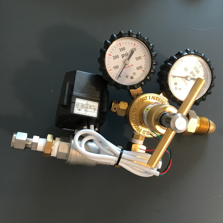
Below: regulator assembly
- Left: compression fitting to propellant tank.
- Center: system-pressurization control valve.
- Right: Regulator to attach to Nitrogen tank.
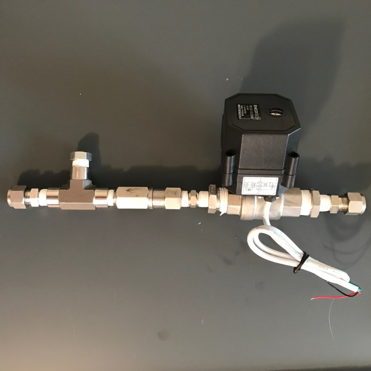
Below: throttle-valve assembly.
- Left: compression fitting to nozzle and check valve.
- Center: throttle valve (motorized ball valve).
- Right: compression fitting to propellant tank.
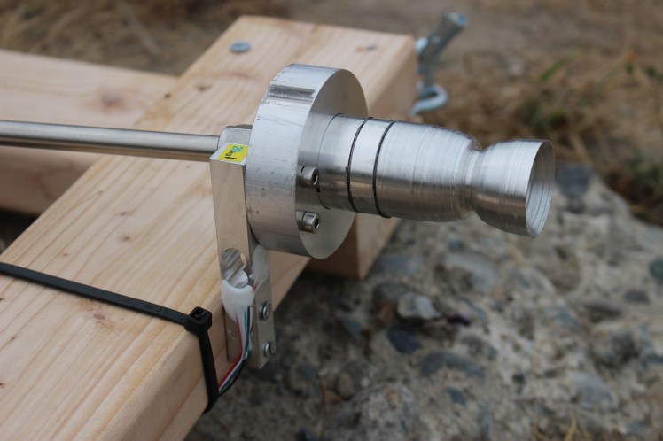
Below: Nozzle assembly
- Left: propellant line from throttle-valve assembly.
- Center: thrust take-up assembly mounted to load cell to measure thrust.
- Right: nozzle
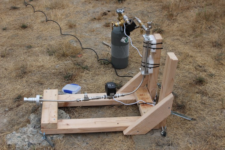
Below: assembled engine on test stand.

Test:
- Pushed citric acid through the system for purification.
- Pushed H2O2 through the system for thrust test.
- Pushed water through the system for cleaning.
Evaluation:
- Rocket produced significant thrust, however data-logger for load cell had gain set too low and did not produce meaningful results.
- No erosion occurred at the nozzle throat; the exterior nozzle thermocouple showed temperatures under 100 degrees Fahrenheit.
- Most of the fuel was already expelled by the time that the throttle valve was fully open. Faster valves would be preferable.
- The Potassium Permanganate catalyst was blown out rapidly during the test (see black specks in picture). It was difficult to get it into the combustion chamber, due to necessary disassembly of grafoil seals. In the future, a silver nitrite mesh would be a good option.
- It would be fun to make an entirely 3D printed version.
